Construction and design
Aerzen positive displacement blowers - more
are twin shaft rotary machines. The two rotors are placed axially parallel to each other and centered within the housing. Timing gears ensure that the rotors revolve without making contact. The rotors are supported on ball and roller bearings. In order to achieve a high efficiency the clearance between the rotors is kept to a minimum and is based on the pressure differential and thermal load expected under operating conditions. In case of larger blowers the roller bearing clearances and the shaft deflection have an influence on the clearance. Larger clearances between the rotors and the end plates compensate for axial thermal expansion at the floating bearing end.
Housing
The housings are made of high quality grey cast iron (GG 20). The blower housing requires no additional cooling, even at high loads. Up to the size GM 80L, the blower feet are bolted on.
Sealing configuration, series GL and GM
These models are designed to convey air or neutral gases. The conveying chamber is sealed from the oil chambers by means of an oil slinger in conjunction with piston ring labyrinth type seals featuring a generously dimensioned central vent chamber (condensate channel), and which plays a crucial role in ensuring that the medium conveyed remains clean and oil-free. The drive shaft is sealed by means of a radial seal ring installed in the housing cover.
Rotors
The rotors are dynamically balanced. Smaller blowers of the sizes GM 3 S - GM 80 L feature steel rotors and shafts (C 45 N), drop-forged in one single piece. Sizes GM 90 S and larger are constructed with pistons made of GGG 40 and steel shafts (C 45 N). Where contamination particles are likely to accumulate during operation, the cavities of the cast iron rotors are capped.
Timing gears
The helical timing gears are tempered, and then ground to an exacting degree of precision. The positioning and fastening of the gears onto the shafts takes place via taper interference fit, guaranteeing both excellent concentricity and reliable adherence.
Special materials
Non-standard materials such as nodular graphite cast iron (GGG 40), cast steel (GS - C 25) and CrNi - cast steel are available for special applications. Special requirements, however, must be clarified with the manufacturer in advance!
Accessories
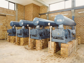
Our blower units normally include the standard components for continuous operation. The installation is effected on flat, load bearing surfaces, elevated floors or steel structures, a rigid installation on concrete foundations is also possible. In most cases the blowers are driven by a three-phase asynchronous motor and - for adjustment of the volume flow - a belt drive. Upon demand special designs as direct coupling, intermediate gearbox or special materials are also available. - more on blower accessory components
Special designs possible at any time.
For more information contact Aerzen Canada |